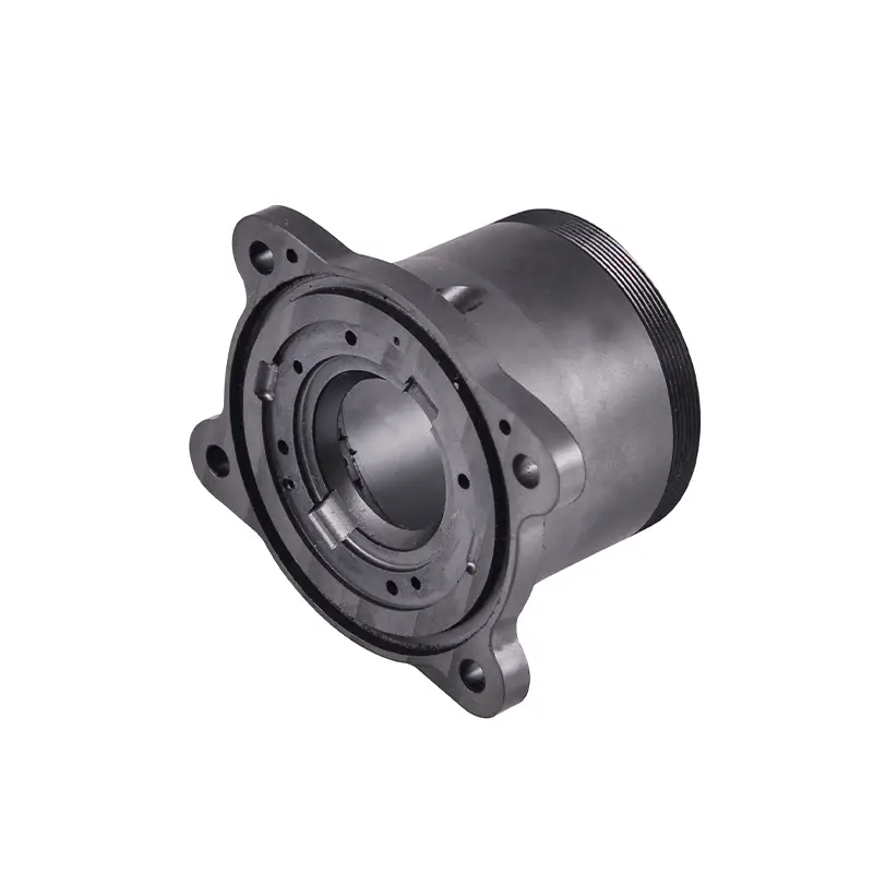
Complex plastic parts can look straightforward in a CAD model but become considerably more demanding when they move into tooling. Ribs, bosses, undercuts, thin walls, textured surfaces, and intricate cores and cavities can all affect moldability, machining, cooling, ejection, and part quality. For these applications, rapid prototype tooling provides a practical way to validate the design before committing to full production tooling.
The challenge is not simply making a mold quickly. The tooling must reproduce critical features accurately while remaining practical to manufacture, modify, and test. This makes mold design analysis especially important during the prototype stage.
Start With Part Geometry and Moldability
Complex geometry should be reviewed before tooling begins. A detailed Design for Manufacturability analysis can identify potential issues involving parting lines, gate locations, ejector positions, wall thickness, tolerances, surface finishes, sink marks, gate marks, and warpage. HordRT provides preliminary DFM feedback with its quoting process, helping engineers address tooling concerns before machining starts.
For parts with deep cores or complicated cavity geometry, the parting line needs to balance manufacturability and appearance. A poorly positioned parting line can increase machining difficulty, create visible flash, or complicate ejection. Early analysis can also determine whether a feature should be redesigned or handled through a separate tooling component.
Manage Ribs and Bosses Without Creating Defects
Ribs improve structural rigidity without requiring excessive material, while bosses provide mounting points for screws, inserts, and other components. However, these features can create localized changes in material thickness.
If ribs or bosses are too thick, sink marks may appear on the opposite surface as the plastic cools. Their connection to the main wall can also influence filling and cooling behavior. Prototype tooling gives engineers an opportunity to evaluate these details with actual molded parts rather than relying entirely on digital analysis.
For complex boss configurations, the tooling design should also consider core strength, venting, ejection, and machining access. Small adjustments to rib thickness, draft, or boss geometry can make the mold easier to produce while preserving the required function.
Design Around Undercuts and Complex Cores
Undercuts are among the most important considerations in complex prototype tooling because they can prevent a molded part from releasing directly from a conventional two-part mold.
Depending on the geometry and expected prototype volume, designers may consider slides, lifters, inserts, or other mechanisms. The appropriate approach depends on the feature location, required dimensional accuracy, material, tooling budget, and expected number of shots.
Complex cores and cavities also require careful attention to machining strategy. HordRT uses CNC machining, EDM, wire cutting, gun drilling, fitting, and polishing as part of its tooling process. After DFM approval, these operations are coordinated to prepare the mold for trial production.
This integrated approach is particularly useful when a prototype contains several difficult features that need to work together rather than being evaluated individually.
Treat Thin Walls and Textured Surfaces as Tooling Decisions
Thin walls can reduce material consumption and part weight, but they also make filling and cooling more sensitive. The gate location, flow path, material selection, mold temperature, and venting strategy can all influence whether the part fills consistently.
Texture introduces another consideration: draft. A textured surface generally requires sufficient draft to release cleanly without damaging the texture or the molded part. The deeper or more aggressive the texture, the more carefully the release direction needs to be evaluated.
Surface finish should therefore be discussed before machining begins. Prototype tooling can help confirm not only whether the geometry works, but also whether the appearance meets the intended product requirements.
Choose Prototype Tooling Materials Based on the Test Objective
Tooling material should match the purpose of the prototype. HordRT lists hard aluminum 7075 and carbon structural steel such as S50C among its rapid prototype tooling options. According to HordRT, 7075 aluminum offers fast machining and can provide a tooling life of approximately 500 to 5,000 shots, while S50C provides an economical steel option that is also easy to machine.
The decision should consider expected quantity, plastic material, feature complexity, dimensional requirements, surface finish, and how many design iterations are anticipated. Selecting the right tooling material can help control both development cost and modification requirements.
Use Mold Trials to Validate More Than Dimensions
A prototype mold should be evaluated as part of the product development process, not simply as a way to produce sample parts. Mold trials can reveal filling problems, deformation, sink marks, flash, ejection difficulties, and surface inconsistencies that may not be obvious from the CAD model.
HordRT describes a trial and inspection process that includes material preparation, mold filling, completed-part inspection, and dimensional quality checks. This creates an opportunity to compare molded parts against the intended design and make informed modifications before production tooling is finalized.
For engineering teams, this feedback can be valuable when several design variables interact. A small change to a rib, boss, gate, or core may affect multiple areas of the finished part, making physical validation an important part of the development cycle.
Why HordRT Fits Complex Prototype Tooling Projects
HordRT combines rapid prototype tooling with injection molding, CNC machining, sheet metal fabrication, and other manufacturing processes, allowing different prototype requirements to be handled within one manufacturing network. Its rapid prototyping service emphasizes quick turnaround, DFM analysis, material flexibility, and cost control.
The company states that it can provide a preliminary DFM report with an inquiry, offers no minimum order quantity, and provides detailed quotations within 24 hours. HordRT also reports ISO 9001 and IATF 16949 certification and production capabilities for rapid tooling and molded parts.
For complex plastic components, these capabilities can simplify the path from CAD review to tooling, trial molding, inspection, and design refinement.
Turning Complex Geometry Into Testable Parts
Rapid prototype tooling is most effective when tooling design begins with the actual challenges of the part. Ribs and bosses require balanced wall thickness. Undercuts require a release strategy. Thin walls require careful flow and cooling considerations. Textured surfaces demand appropriate draft and surface planning, while complex cores and cavities require a machining strategy that supports accuracy and efficient modification.
By addressing these factors during DFM and validating them through mold trials, engineering teams can reduce uncertainty before production tooling. With its combination of DFM analysis, rapid tooling, machining, molding, and quality inspection, HordRT provides an integrated route for developing and testing complex plastic parts with greater control over time, cost, and manufacturability.